Tuesday, December 15, 2020

Chapter 22 Electrical - Audio Panel - headset jack install.

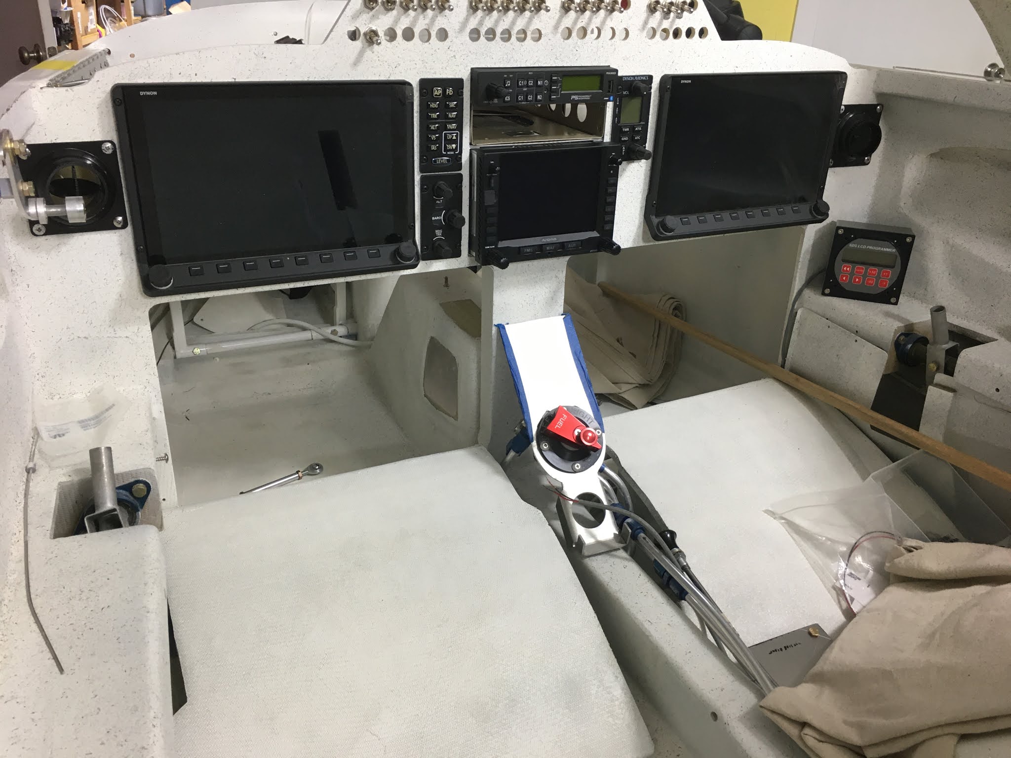
Test fitting.  Still deciding where to mount the SDS interface.
PS Engineering unit with custom harness.
Plate for audio jacks.  Version 2.

Printing on the wires identifies function, jack, pin and colors.
The wires need to be fed through this back shell before pinning the connector.  Doh!
One connector done.  The other needs depinned. 
Unit secured in tray with jacks connected to the back plane.
Test fit is good.   Jack doesn't interfere with canopy strut.

Neat features.  Multiple music sources available.

Paired a phone and tested charging, bluetooth streaming music and caller ID.  Phone capability is handy for IFR clearances over the phone and other pertinent calls.  

Thursday, December 3, 2020

Chapter 22 Electrical System progress

The nose gear harness was a rats nest.  The previous builder had some assistance from Jack.  Not all the colors matched the schematic.   Took an evening to untangle and lace it up nice.  Tested the emergency extend function.

I soldered and used heat shrink on some of the bare splices in the nose gear harness. 

There's approximately 70 wires for probes, EI and EFI not including the shield ground wires.

The white enamel paint on the motor mount is going to need touched up.


Sunday, November 15, 2020

Chapter 22 Electrical - Firewall Bulkhead connectors and MAP sensors

Two 37 pin Amphenol bulkhead connectors penetrate the firewall.

Dynon and 2 SDS MAP sensors mounted.

One 37 pin Amphenol cannon plug is for the CHT and EGT wires.

Mostly SDS and some Dynon EFIS wires are in this cannon plug.


Chapter 23 Oil Cooler

The plans oil cooler mounting locations are mounted to the firewall at the top of the cowl or on the bottom cowl.   I opted for the top since the exhaust area is lower pressure than the NACA inlet on the bottom side of the aircraft.  The pad mount alternator will get cool air.  Also, when parked the top opening will allow convection air to pass through and cool the auxiliary case engine area.
The oil cooler will be mounted in the top of the cowl position above the pad mount alternator.  This will allow access to change the oil filter.  The bolts holding the tank vent manifold will screw into nutplates on the oil cooler mount.   The plans specify to mount the cooler 1.5" below the lip at a 10 degree angle.

I used 2024 1 x 1.5 Angle and .75 x .75 Angle stock.  Floating nut plates receive the bolts through the firewall and vent manifold block.

Above the engine mount, the .75 x .75 angle stock rests and can be secured with an Adel clamp.

45 degree steel fittings will be installed.   The outboard mount needs to be fabricated and installed.  Box tape and scrap foam will be used as a form for the duct.


Test fitting with the center bottom brace resting on the motor mount.

View from underneath.  Top cowl oil door hinge is to close to the outboard flange of the cooler.

Tilting the cooler a little more improves clearance with the oil door hinge.


Shortened the center bottom brace, installed nutplates and attached an Adel clamp.

Lower inboard bracket with nutplates is installed.  Attached to motor mount with an adele clamp.

Top center brace is drilled and attached.

The nutplates are to small for the jig so didn't get the holes perfect.  Fixed them with a Dremel.


Borla fuel pressure regulator is mounted to the bottom bracket. I decided this location had several advantages over other locations.

Inboard view of fuel regulator.

Test fitting reveals the oil dipstick clears (barely), but a benefit is when changing oil, a the line can be disconnected to drain the cooler into the oil dipstick tube using a small funnel.  The duct also was very close to the oil door hinge on the top cowl.  The glass duct construction required multiple layup/cure/trim iterations.  Would have been easier without the engine mounted.


Inboard view of the regulator/oil cooler/duct and bracket bolted to the fuel tank vent manifold.

Last night I ordered Aeroquip 466 hose assemblies (almost $1K) with stainless steel fittings:
AN4- Straight - Straight (fuel pressure sensor hose) 14"
AN4- Str-Str (oil pressure sensor hose) 7"
AN6-Str-90 (fuel reg to FW) 20"
AN6- Str-Str (fuel reg to fuel manifold) 13"
AN6- Str-90 (fuel manifold to FW) 32"
AN8- Str-Str (oil cooler return to engine)  18"
AN8- Str-Str (engine oil out to cooler in)  30" 
Fuel regulator mounted to oil cooler bracket.


One line was a little to short so I added a 45 degree M-F adapter.  The dipstick clears the AN8 oil line.

A better view of the outside lower angle support using an Adel clamp and an L bracket.

Fuel lines routed to the pressure regulator.  The return line feeds off the bottom of the regulator and goes to the firewall bulkhead connector.


Tuesday, October 20, 2020

MODS


Most of these have been implemented, some aren't planned:

Marc Zeitlin's nose gear actuator clamp - (installed)
Crankshaft bearing seal retainer - (installed)
Click bonds (aileron and rudders  - completed)
Denise Oelmann rudder pedals (completed)
Brakes (Matco)
Matco lay-down master cylinders (completed)
Hidden Rudder bell horns (completed)
Electric nose gear (Wilhelmson) (completed)
Trailing Edge Wing Fences  (complete)
Glass panel - (Dynon Skyview installed)
Teflon aileron and rudder hinge pin tubes. (completed)
Electric belly brake (completed)
Site gauges (Vance Atkinson) (completed)
Fuel probes (Nick Ugolini) (completed)
CG strakes (completed)
CG HD IO-360 Motor mount (Cozy Girrrls) (completed)
CF boat tail cowl (Freeflight Composites) (completed)
Leg fairings (Eureka CNC) (completed)
Electronic Ignition -SDS EM5(installed)
Electronic Fuel Injection - SDS EM5 (complete)
Belleville Washers  Solon Mfg. for propeller  (installed)
Retractable step (pending)
Fuselage access door elimination/modified canopy latch
Auxiliary/enhanced cabin heat (Plans heat in use during Phase I seems adequate at this time.)
Non-plans taxi/landing light (undecided on location/type)
Non-plans Pitot tube (currently in the nose)
Vortex Generators (slower landing speeds-purchased Stolspeed Vortex Generators from ACS-installed briefly during Phase I but removed them.)
Fuel control valve moved forward. (completed)
Removable canard cover (easier removal of fuselage cover for instrument access-completed).
Electric Pitch and roll trim (completed)
Widened NACA inlet throat (completed)
Brake heat shield temp sensors/Dynon panel widgets added (completed)
NACA Diffuser - (ref CSA Newsletter Set/Jul-03.pdf page=29) (completed)
No lower cowl baffling/ramps.  (update- added plans type baffle in bottom of cowl and have modified it several times to balance CHT's.)
Aerocomposites "modified Defiant" wheel pants (installed-primed)
Balancemasters dynamic balancer - installed.  https://www.balancemasters.com/aircraft

Landing/Taxi lights.  Inclined to install them on the outboard leading edges like Nick U has.  


I've waffled on doing this.  The Dynon Skyview "gear" function has been working well.  It's probably saved one gear up when I was distracted and didn't lower the gear:
Marc's auto nose gear extend system:https://groups.google.com/forum/#!searchin/cozy_builders/auto$20extend$20system%7Csort:date/cozy_builders/jNWtOH_07pg/CqzHC-E-EwAJ
Link to photos and drawing:
https://www.dropbox.com/sh/fhx3yrl6i60vck2/AAAdnLomXYIbR-9Q8Oa7VGRTa?dl=0


Not planned:
Forward Hinged Canopy (adds a little more forward CG, side hinges were already installed.  One disadvantage of the forward hinged canopy is reduced visibility while taxiing)
Blended winglets (maybe add fairing instead)  


No winglets
Larger rudders
Eliminate rudder pulleys on firewall by rerouting rudder conduit.

Thursday, September 3, 2020

NACA Diffuser

 A CSA article (CSA Newsletter Set/Jul-03.pdf#page=29) specifies that a (not per plans) NACA inlet diffuser needs to double the inlet area and use a 14" radius.

The inlet into the cowl measures 4x15 (60 sq. in).

Increasing the outlet
to 7x18 yields 126 sq in.   

Using a 14" radius, the exit is at about 6.5" from the inlet.


Before trimming, test fit before glassing in flanges and adding a stiffener. 


Trimmed off the edges, added a stiffener and a flange to seal against the firewall.


Tuesday, September 1, 2020

Electric Nose gear pin update

Received these from Jack for the electric lift pin update.   Designed to help retain the bolts from loosening.


Wednesday, August 5, 2020

NanoVNA - winglet antenna

The screen is a little cluttered because I left everything default.  The yellow line depicts the CH0 input that's connected to a winglet antenna.  The yellow 1 marker is at 117.043 Mhz.  Later I decluttered the screen and added the SWR graph.  There's YouTube videos how to use this.

Monday, July 27, 2020

Chapter 23 Baffles

Almost per plans...


*another update....a couple cracks appeared on the #1 & #4 baffles.  It's probably because I put those parts under the #2 & #3 baffles and screws which pinched and stressed the parts.  They should have gone on the outside so cylinder head movement wouldn't crack them.  Here's what I did ...
https://cozy1537.blogspot.com/2023/11/baffling-cracks.html

*update... See the updates for First Edition plans/Mandatory changes.   The exhaust baffles should be made with 1/8" aluminum.   This update isn't in the Third Edition Plans.
http://www.cozybuilders.org/newsletters/MKIV_corr_by_chap.html


Vance and others suggested using .032 aluminum instead of .025 to reduce cracking.  Some posted they got the Vans kit and only used some of the parts.

I started making baffles using the plans but with tapered fins on the cylinder barrels, will have to modify the cylinder fin baffles. 


Here's a template for ECI tapered cylinder baffles if using the Vans baffle kit:
http://www.prettybits.com/files/Tapered_Cylinder_Baffle_Extensions_Continental-ECi.pdf

https://images.app.goo.gl/SgHcrgonccf1auMb6


The first parts were fairly easy to make.

Put the #1 & #4 baffles on the outside of #1 & #2 to allow for expansion otherwise they'll crack near the screw.


The top cowl makes contact.  It's easy to see in the rear of the cowl.

I used a sharpie on a stick to mark cut lines.  Initially I trimmed for 1/4" clearance but  later, the plans specify 3/4 to 1.5" clearance over the heads to allow for engine movement.

A typical problem I have is getting tired and making mistakes.   I was using the small M drawing and didn't realize that this template and was split onto another page.

The plans template was close but I changed the cut/bend lines a little to match these heads better.  I'll round the corners, debur and sand the edges.

Nutplates were installed on the #3 cylinder head baffles to help hold the forward sections in place.

Nutplates installed on #4 cylinder head baffle.

Another area the plans templates don't match due to a different starter and alternator.

The plans template didn't quite match the #4 exhaust pipe so I used some scissors and tape to adjust the template.  The SDS fuel injector protrudes.

The band saw has size/width limits of a little over 13".

The aft baffle at the #1 cylinder.

A bottom baffle support bracket that bolts to the starter. (Not in the plans)

The top left brace was added to stabilize the top of the aft right baffle.   The per plans baffles would be attached in this area.

Tapered baffles with the hanger reinforcement wire and small beads of silicone adhesive to reduce abrasion.

Safety wire routed through some Nylaflow.

Modified M34 #6 template.


The pipe here goes to the prop governor.


#1 cylinder fin baffle test fit

There's a 1/4 x 20 hole on the case behind the alternator, so made a bracket to hold the barrel baffle and have a place for a nutplate to help secure the aft baffle.

This one is per plans.   It wasn't clear to me what/how to  use two double loop safety wires so I twisted to .041 wires together as one and threaded it through the 1/8" holes.


A nut plate jig (they're not cheap) makes perfect holes.  There's no nut plate jigs for the small footprint nut plates though.

A template posted on the RV forum was used for the barrel fin baffles.
The modified template #1 was used to make the interhead baffle #6.  

A 1 3/4" hole saw in a drill press.   Material clamped firmly.


The gap on the right aft side was larger than desired, so taped some paper in, then marked the cut line with the sharpie.


A patch/doubler was added on the bottom right aft to close up the gap.


The intercylinder head baffle is not per plans but is similar to the plans part on the left side of the photo.


The right aft baffle's movement was limited by adding a piece that stops against the spacer on an engine through bolt.  Dabs of RTV will be used to stop rattling and wear.

Alternator collar template.   


Heavy aluminum tape was used to seal around the alternator and starter.  Some large washers capture the collar around the starter.


A dab of RTV between the baffle and tube should eliminate rattle and movement.  Baffle seal helps against the case in this area.


Large washers, screws and nut plates help secure the alternator collar, but allow adjustment.


Alt text
A nutplate mounted to a little pedestal was added to the aft baffle for a screw through a starter tab to help support the aft baffle.   The aft and bottom baffles can be removed for maintenance on the alternator or starter.

The outboard area next to the pipes needs blocked off.

Foam was microed in and will be glassed on both sides of the cowl.