Showing posts with label Chapter 21 - Strakes. Show all posts

Tuesday, January 15, 2019

2019 01/15

Andair Dual Gang Fuel selector valve, SDS fuel pumps, 40 micron fuel filter.   Click bonds will be used to secure the fuel pump. *Update-Click bonds were to large so I used rivnuts secured to washers that are floxed into the floor.   The thigh support will be secured with hinge pins to allow access for maintenance.
Completed another leak test and repaired a small leak on the left tank where the fuel probe line came in under the longeron.


Pilot side of valve/banjo valves.

Close up of lines and banjo valves.


Matco brake lock valve had some metal shavings in it.   Need some AN-3 1/8" nipples and cable to complete its installation near the pilots left leg.

Friday, January 11, 2019

2019 01/11

I've worked on a variety of things this week while waiting for orders to arrive.

Mounted the oil temp sensor in the 90 degree oil filter adapter.
Terminated the SDS (Bosch) throttle position sensor.  I crimped the wires but ended up soldering them since I could pull the wires out of the crimp.
Installed the P5000 quick oil drain plug.
Finished making the cabin fuel lines and leak tested the fuel selector/lines and tanks.   Found air leaking from the left tank where the fuel probe line came through under the longeron.   Drew a vacuum on the tank, used a hypo to fill the leak with epoxy.

Started eyeballing how/where to mount:
18 row oil cooler (near the plans location -top cowl-should work)
3 MAP sensors (2 for SDS, one for Dynon)
SDS Intake air temp sensor
Oil and fuel pressure sensors.
Fuel pressure regulator.
Battery and Starter solenoids.
Throttle quadrant/cable.


Glanced at the Aveo Ultra strobe/nav lights manual and noticed they are TSO'ed.
Copied the XP-382 engine manual and Aveo light manual to Google docs and linked them to blog entries. 

Contacted Ross at SDS about several items.   I was missing some of the male Weatherpak pins needed for the injector harness and also had questions about which Hall Effect sensor should connect to the primary ECU and which one should go to the back up.   Ross offered to send some pins and advised that the calibration procedure would synch the sensor with the ECU.   I think when we ran the engine at Kamloops, the top sensor went to the primary ECU.   They kept the harness for the test stand and replaced my connectors which is why I can't tell.   I should have pins here on Wednesday from another vendor.

I'd ordered about 15 items on-line through AeroPerformance for "will call pick up" and had checked on delivery.   A bunch of the items had not been processed, but some were.   I don't quite understand why everything wasn't ordered but the local gal at the counter advised me next time to let her know and she'd get everything ordered.  I wanted to pick up at the store to avoid having packages delivered during the holidays when we were gone.

Del City has a bunch of overstock/discontinued items so I ordered a bunch of switches that are normally $4 for .60 each.   I was pondering getting a 60 amp breaker rather than using the ANL fuse.

My Nav/Com was shipped but there was a snafu on the delivery address.   UPS shows they received an address update but also show delivery tomorrow.

It's been cold and rainy, but the heater is keeping the shop above 60.  There's been respiratory crap going around and it finally caught up with me.


Saturday, December 9, 2017

Chapter 21 Strakes - Fuel caps

These are not the plans Usher fuel caps.  Several folks recommended the Newton caps because they don't leak and you can use just your fingers to remove them for fueling.  Locking versions are available.  The two hole saws (2 1/4 and 2 1/2) worked well.   Cut the 2 1/4 hole through the top layer first but not through the inside skin.   Then make a cut with the 2 1/2 hole saw just through the top skin and then clean the foam and micro off the glass where the flox needs to bond.  In retrospect, installing these caps before glassing the top skins on is probably better.   You can more easily decide where you want the caps to be.   Also you'll have less debris in your tanks.  I'm not sure how well the caps would hold pressure for the leak test.  Edit-they held pressure fine. 
Don't try to clean the debris out with a vacuum.   The air rushing into the opening will scatter particles everywhere in the tank.   Vance recommended this duct tape trick.  I also used some wet paper towels to mop up the junk that fell in.  A long skinny dowel worked good for dabbing with duct tape and "mopping" with the damp paper towels. 


Flox filled in the gap between the skins for a glass to glass bond.  Then the neck was cleaned with alcohol and then buttered.   A short piece of pop sickle stick with electrical tape just long enough to catch the inside flange was wired to the longer stick.   The neck was buttered with flox and gently allowed to settle down through the flox.  The extra that squeezed through dropped onto a paper towel inside the tank.   Visible flox that was dripping was carefully extracted before it hardened.   The neck needs to be oriented properly.   The top surface of the cap will be slightly higher than the strake surface when they're installed.

Sunday, September 24, 2017

Chapter 21 - Fuel probes


I had some of Nick's earlier probes that required larger holes to be drilled at the top to help avoid getting clogged with flox.   Instructions are on his web site.  


Princeton modules interface with the probes.

Decided after cutting the first hole that it wasn't the best location.

I used a long skinny small drill bit to make the hole for the probe wire and used safety wire to pull the probe wire through.


Sunday, March 26, 2017

Chapter 21 - sumps & lines


 The sumps are on and ready to fair in after the cowl is on.


Right tank fuel line and return lines.   The return line opening is under the fuel screen to allow bubbles to escape from the sump.

*Not per plans.  (Tub is inverted.)   Carved the clearance pocket for the joystick and rerouted the rudder conduit slightly.
*Not per plans.  The Andair dual gang fuel valve will mount towards the front of the console.  90 degree banjo fittings (special order) will better accommodate the lines coming in from the left and right sides under the thigh supports.

*Not per plans.  The vent lines terminate into a 7 port manifold after the SS firewall is in place.

Wednesday, March 15, 2017

Chapter 21 fuel selector and lines

*Update - this is an older post.  I'm mounting a dual gang selector forward on the console.

Chapter 14 is on fuel systems:
https://www.faa.gov/sites/faa.gov/files/2022-06/amt_airframe_hb_vol_2.pdf


In the plans it says to use 1 BID tapes to support the fuel lines to the selector.   It looks like most builders have put in the click bonds with Adel clamps.

Since I'm installing the dual gang selector mounted on the console, the routing of the two lines going to each of the tanks (fuel and injection bypass) it looks like routing along the side by the conduit up to the front thigh support area will help avoid making some pretzel shaped bends that would be required if routing over the heat duct.   The lines to/from the engine would route per plans over the heat duct back through the firewall.  The bottom gang will be used for the fuel going to the engine to help avoid low spots in the path. when flying straight and level or parked on the ramp.  The lowest points when setting level will be the drains on the sumps and the gascolator.

All that being said, I weighed an approximate amount of click bonds and am speculating that with the nuts and clamps needed for six lines, it will be hard to beat the weight savings of 1 BID tapes.   Near the selector where the lines would need to be disconnected would be good for some click bonds.

I found a table that said 3/8" should be supported every 16".

The Andair Gascolator has 70 micron screen with a lockable valve to help facilitate draining tanks without pulling fuel lines loose.


Sunday, November 20, 2016

Chapter 21 - November update

The top outside skin isn't glassed yet but I'd rather see if there's any tanks leaks now rather than later.
The right tank has held pressure for weeks now but does vary up and down with the ambient temperature and barometric pressure changes.

17" vacuum 
17" pressure.  Hmmm.  Someone drew a Christmas tree on the foam.  Little helpers...


Here's a link to a discussion on our Cozy Builder group regarding pressures and testing:


Tuesday, September 6, 2016

Chapter 21 Strakes - September 2016 - updates

(update) *Not per plans/Cozy Girrrl Strakes.  I  added an additional rib (not seen in many of the photos) to prevent the problematic sag between the outer and inner rib.   Check the template updates for the ribs.  The inboard rib has an additional 1/2" loft my plans and ribs I built. don't have.  :


T-hats on ribs untrimmed with peel ply removed after pulling the top skin off. 


T-hats trimmed with Fein multi-tool.


Bonding skin panels together.

Elf at work.


Capacitive fuel probe.  Fuel site gauge mounts in the cabin.

Holes drilled for site gauges per instructions.

Top left strake skin with box tape so it can be popped off when the T-hats cure on the strake ribs.

Peel ply applied where T-hats will mate with top skin.

Wet BID tapes applied to ribs/baffles.   Then top skin is put in place, then the BID tapes were pressed against the box tape on the top skin.   It's probably easier to use the sandwich method to wet and apply the tapes, but  working overhead was a bit of a pain.


Half inch wide masking tape applied between cuts, then micro is applied to fill the voids in the bent foam.   Tape is removed before micro cures.

T-hats with peel play after cure and the top skin is popped off.  The additional rib is seen here. 

The R33 and R57 templates were made with the thickness of the skins added to ensure the left and right sides were symmetrical with the skins on the ribs.


This is one of the harder parts to mate the skins together.   When the leading edge is curled down, it pulls away leaving a gap at R33.


Pour foam.

High grit and slow speed worked fine on the pour foam.

It would have been easier to cut this hole before glassing the TLE in place.

Multiple layers of EZpoxy applied several hours apart to the top skin.

The gap at R33 appears here.   Pop sickle sticks helped control the shape of the top skin.


A piece of safety wire pulls the pop sickle stick down to conform the skin.   If you use this method, be sure to get some wet flox into the hole left by the safety wire when you glass the skins on.


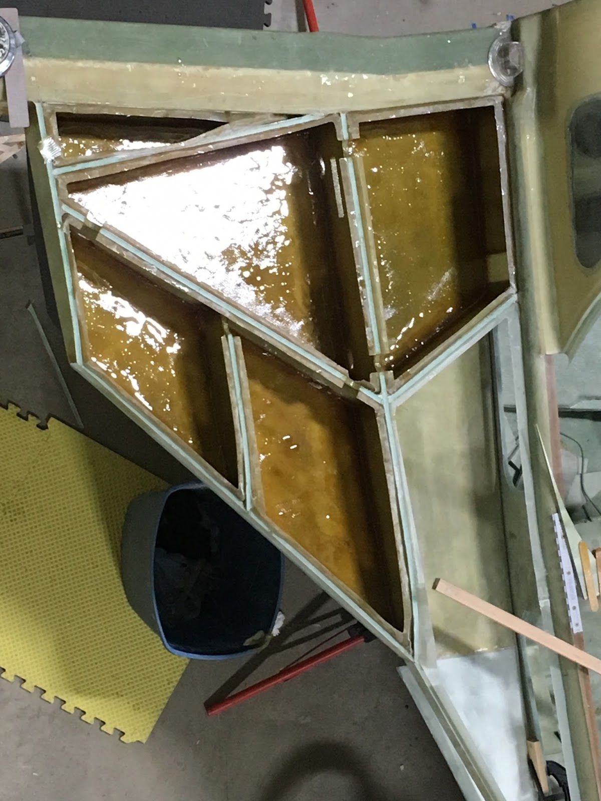
EZpoxy (amber colored) for the fuel areas and MGS (green) used elsewhere.


A half a stainless steel drain screen provides plenty of surface for fuel to flow through and stop large debris. 


Two vent lines run into each tank.  One to the leading edge and the other to the back of the tank.   Plans say to run one to the leading edge.   Reports of siphoning or raw fuel venting were circumvented with this "mod".

The trick to drilling an additional vent hole in the rear vent line is to clamp a washer to the line to guide the drill bit.   The rear vent line goes through R33 so this hole allows air to escape  if there's a bubble on the inside of R33.  The other line terminates above the leading edge drain.

BID tape was applied to secure the vent lines inside the tank. The additional rib is seen here.

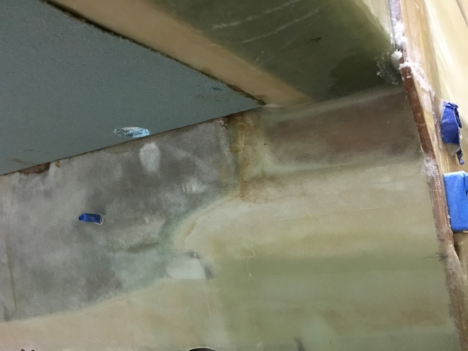
The sump hole and fuel line (with blue tape).   The bottom outside skin is not yet glassed.

The right bottom skin is almost ready.

Site gauge is floxed in.

Fuel drain parts/prep. 

The output stands are very adjustable and handy.

Plenty of clamps and several types of stands hold the bottom skin in place.  The bottom of the strake is flat but slopes so fuel will drain to the sump.   

View of the right strake from above with T-hats trimmed and bottom skin glassed on.


The dowel rods and the Paulk work bench help secure things.

West 407 filler is reddish colored.

It will be easier to sand the inside of the baggage area before the top skin is glassed on.

Clam shells on in preparation to flip the project.

The "space shuttle" pose.   It's easy for one person to stand this up but better have one or two more helpers to go the rest of the way over.

UNI going on the left bottom skin.