Check the templates for corrections:
http://cozybuilders.org/cad_files/Cozy_MKIV_M-Sup_1.2_Draft.pdf
The strakes will be modified "Cozy Girrrl style" which provides elbow room in the cabin and an alternate path for antenna cables and the wing tip light wires. A few sheets of foam were prepared a few months ago and set aside with the peel ply still on.

I pulled them out and used the table saw to cut to the appropriate widths where R33 and B33 are one piece rather than having to bond them together. The 17.4 water line is marked on the ribs and bulkheads as well as the wings & fuselage using a laser.

I used a couple of hole saws with a jig in a drill press to make the openings in the ribs and bulkheads.
Since the top of the strake is flat (on my copy of M drawings)*, the pieces can be assembled upside down on a flat table. *New M-drawings now show a "loft" on the top of R57. If you use the modified R57, you'd have to raise the baffles and R33 about 3/8" to use this method. I think that builders that made a rib on the end of the spar that matches the contour of the wing have slightly mitigated not having R57 with the "wing loft".

The R57 rib's leading edge sets back about 3.5" further than R33. EZpoxy is being used for the fuel tank.
I clamped a board on the bottom side of the spar to support the ribs. I used bondo to hold some scrap boards on the top of the longeron the end of the spar. Shop light stands and pop sickle sticks worked good to get the ribs aligned on the water line. I also marked BL 33 and BL 57 on the canard and ensured the ribs were still parallel. The build lines were found and marked on the spar by finding the center line on the back of the firewall. There's also supports under the winglets to keep the whole thing steady while the glass cures. The additional bulkhead* where the fairing block goes is held in place with bondo and pop sickle sticks. *Some builders have had a sag and this was recommended to mitigate the sag by the Cozy Girrls.
The foam for the skins between BL 33 & BL 57 are cut and waiting for the inside glass and will be shaped to the ribs after cure.

|
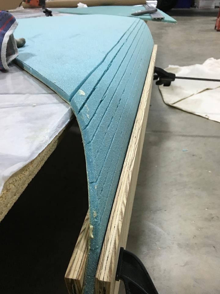
| Cuts through foam 1/2" apart - CG suggestion. Plans say 1". |
 |
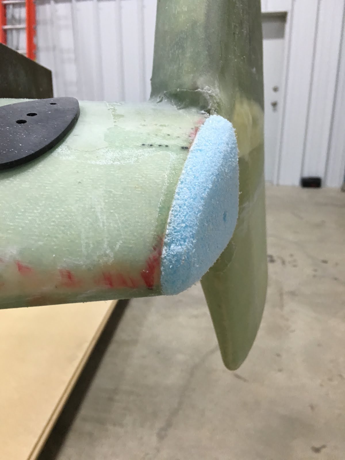
| Test fitting. BAB, TTE, OD and TLE not installed yet. Was to cold for Epoxy work. |

 The dynafocal type 1 mount for the fuel injected 360.