Typical mags fire the top plugs on one side and bottom plugs on the other side. I looked at one of the older Jeff Rose EI systems and it is wired this way. The Fly EFII system specifies top plugs to one coil and bottom plugs to the other coil. The ignition switch on traditional aircraft have Off/Left/Right/Both. I'd noticed that some experimental/home built aircraft switches were labeled Top/Bottom.
The cylinder cooling fins have different depths on the left/right sides of the barrel.
This is my supplemental builders blog for a Cozy Mark IV which is a 4-seat, single engine, homebuilt light aircraft designed by Nat Puffer, with parts and plans supplied by Aircraft Spruce & Specialty Co. The aircraft is built from plans using basic raw materials. It is not a kit aircraft, though many small parts are available prefabricated. The Cozy is similar in design and construction to the 2-seat Rutan Long-EZ, from which it is derived, with approval from Burt Rutan.
Chapters (Blogger Labels)
- Chapter 01 Description and Introduction (1)
- Chapter 02 Bill of Materials (1)
- Chapter 03 Education (1)
- Chapter 04 Fuselage Bulkheads (1)
- Chapter 05 Fuselage Sides (1)
- Chapter 06 Fuselage Assembly (1)
- Chapter 07 Fuselage Exterior (1)
- Chapter 08 Head Rest and Seat Belts (1)
- Chapter 09 Main Gear & Landing Brake (1)
- Chapter 10 Canard (1)
- Chapter 11 Elevators (1)
- Chapter 12 Canard Installation (1)
- Chapter 13 Nose - Nose Gear & Brakes (4)
- Chapter 14 Center Section Spar (1)
- Chapter 15 Firewall (5)
- Chapter 16 Control System (2)
- Chapter 17 Pitch and Roll Trim (2)
- Chapter 18 - Canopy (1)
- Chapter 19 - Wings/Ailerons/Attach (1)
- Chapter 20 - Winglets & Rudders (12)
- Chapter 21 - Strakes (11)
- Chapter 22 Electrical System (17)
- Chapter 23 - Engine Installation (11)
- Chapter 24 Armrests (2)
- Chapter 25 - Finishing (7)
- Chapter 26 Upholstery (1)
- Cozy Builders (2)
- Flight Testing (1)
- Landing Brake and Center Console (2)
- M Drawings (1)
- mods (7)
- Seats and Fairings (1)

Sunday, December 16, 2018
Sunday, November 11, 2018
Sunday, November 4, 2018
Things I learned this week....
You can't cut stainless steel with an Oxy-Acetylene torch. The metal pools and blobs fly when you hit it with Oxygen. Oddly after discovering this, I found this video titled Dummy trying to cut stainless with a torch.
The Type - K yellow insulated lead thermocouple wire can't be soldered with rosin core solder. It's made of nickel and chromium. There's a new Type N wire. http://www.thermometricscorp.com/thertypk.html
If you make a joke (regarding aviation) on social media, someone might complain to the FAA and they're obligated to investigate. Recent account from YouTube "Just Plane Silly" channel story here: https://youtu.be/P0Fs_RI4Hok
Tuesday, September 25, 2018
Chapter 15 Firewall & 22 Electrical - EI/EFI, Dynon EMS, ACK ELT, Princeton Fuel module mounting
The Dynon EMS module and SDS EI/EFI modules need to be mounted on the cold side of the firewall. Mounting them on a removable shelf that is cut to still allow quick access and inspection of the engine mounting bolts and hard points should provide for easy maintenance and changes to be made in the future if needed.
The ELT needs clearance for the antenna, and two small cables (DIN for GPS and remote panel). |
The dual SDS controller has two relays that also need to be mounted. There are 6 connectors on this module. |
The rectangular hole for the bulkhead connectors and round hole for cabin heat are visible here. |
A couple of removable plugs for leg bow inspection were made by using a 4.5" hole saw and cutting from scraps of left over strake material. The foam will be microed. |
BID covered strake foam shelf was bonded to the round covers with West 704 filler. |
The Princeton modules will mount on the triangular space. |
The orientation of the modules is limited by the available space. |
Two Amphenol 37 pin connectors are mounted to a plate that covers a rectangular hole that is large enough for the D-connectors to pass through. A nut plate is on the cold side of the firewall. |
Monday, August 6, 2018
Chapter 22 Electrical System - auxiliary sensors
Unused Dynon EMS ports can be used for additional data.
This would be handy for reading the delta air pressure and temp across the oil cooler, cylinders etc.
http://wiki.dynonavionics.com/Making_your_own_sensor_definitions
http://dynonavionics.com/cgi-bin/yabb2/YaBB.pl?num=1291258674/1#1
http://dynonavionics.com/cgi-bin/yabb2/YaBB.pl?num=1268164287
This would be handy for reading the delta air pressure and temp across the oil cooler, cylinders etc.
http://wiki.dynonavionics.com/Making_your_own_sensor_definitions
http://dynonavionics.com/cgi-bin/yabb2/YaBB.pl?num=1291258674/1#1
http://dynonavionics.com/cgi-bin/yabb2/YaBB.pl?num=1268164287
Monday, June 18, 2018
Chapter 15 Firewall - cutting and fitting
A deviation from plans is to use Stainless Steel rather than Aluminum.
Stainless can be hard to work with. The hole saw grabbed and tore the metal a little here. This hole was just for the knock out bolt. Fortunately, the knock out cut this part out. |
The sheet is clamped in place. The cardboard helps align the knock out. |
A uni-bit seemed to drill holes pretty well without tearing. A sharpie marked the stop depth on the bit. |
Still needing a little trimming, but is lining up pretty well. |
Stainless Steel parts from Cozy Girrrls. Not all holes are drilled. |
Saw this technique either on an EAA video or another metal builder's site. |
Cleco clamps hold the paper to the pulley so the holes can be marked with a sharpie. Small dots mark where the cotter pin holes need to be. |
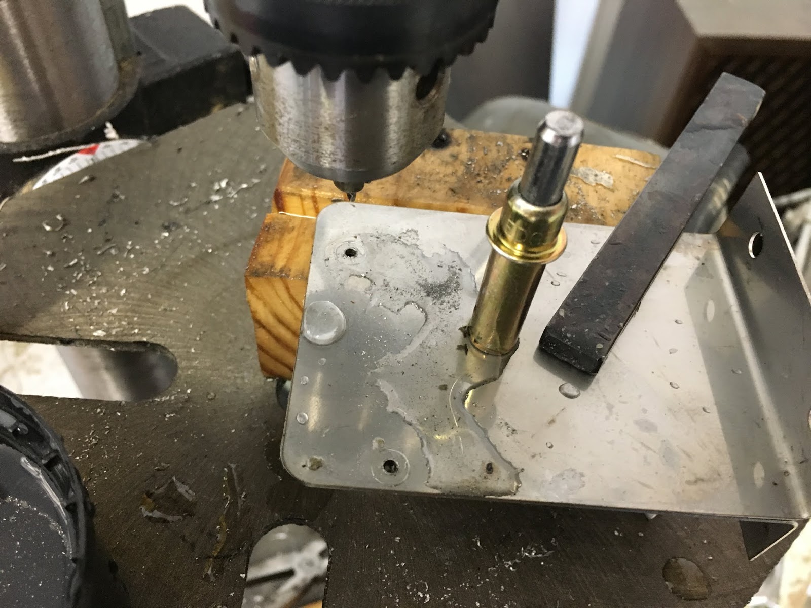
Keep the drill bit cool (I used water) and take your time. These little holes each took about 10 minutes. Black carbide drills work. |
Wednesday, June 13, 2018
Flight Testing
Links to FAA Flight Testing Advisories:
https://www.faa.gov/news/safety_briefing/2014/media/SE_Topic_11_2014.pdf
https://www.faa.gov/documentLibrary/media/Advisory_Circular/AC%2090-89A.pdf
https://www.faa.gov/documentLibrary/media/Advisory_Circular/AC_90-116.pdf
EAA Webinar on the Flight Test Manual:
http://www.eaavideo.org/detail/videos/homebuilding/video/5993410710001/webinar--introducing-the-eaa-flight-test-manual
Here's a link to Kevin Walsh's "Experimental Aircraft Flight Test Protocol":
http://www.cozybuilders.org/docs/Cozy-MKIV_Flight_Test_Protocol.pdf
I'll need to do some editing for mine, but it is really thoughtful of others to share with the group.
I've been reading this and will plan on using the data recording of the Skyview system to help reduce work load. Also think I may ensure the Auto Pilot is working earlier in the protocol to help reduce work load and improve the accuracy of the flight tests.
Adding some notes here that will be incorporated:
Fuel Injection /Electronic Injection - Dual ECU Switch
When running dual ECU boards, this toggle switch activates relays which switch operation of the injectors from one ECU board to the other. In normal operation, one board is always firing the top spark plugs, the other fires the bottom plugs. The ECU select switch only switches the injector connection over to the other board. If one ECU board fails, you’ll lose one set of plugs but the engine should continue to run.
The recommended ECU checking procedure is to start the check on the backup ECU. At idle, Switch the ECU selector switch from Backup to Primary. If the engine continues to run, both ECUs are working. Now you can switch coil power off on the #1 coil pack. Switch that one back on and then switch off #2 coil pack power. If the engine continues to run, both coil packs are working.
Be sure to check that both coil power switches are back on prior to takeoff.
Wednesday, June 6, 2018
Chapter 17 - Vance Atkinson's springboard pitch trim
Vance's canard is unique and shows a universal joint that isn't on the plans Cozy IV. Rather than a manual rod, an actuator with feedback will be installed. I don't think I'll need the component that mounts on the wheel well if the actuator has enough force. It seems its purpose was to reduce the travel distance of the T-handle and to bias the trim so pulling the handled would provide up trim rather than down.
Tuesday, May 29, 2018
Chapter 23 Engine Installation - prop, extension, Step 3 cowl
Catto 68" diameter 78" pitch prop with nickel leading edges and erosion tape. |
The blocks had to be moved in order to apply the BID that lays up in front of the cosmetic piece. This particular area of the cowl lips were a little proud and met the wrath of the belt sander. |
Pop sickle sticks and hot glue worked pretty well and was easier to remove than Bondo. |
3 BID curing while the trailing edge is shimmed up to help correct a tendency to sag.
The plans construction method for the cowl lip is to attach foam blocks to the inlet and carve the foam to this shape. I opted to use a 1x2 piece of PVC foam and a belt sander. |
The cowl wasn't made to accomodate the scoop for the NACA inlet. The lip has to come down and inch. I cut the cowl back 7" to help make a ramp for the scoop that won't be to draggy. |
Prepping the foam lip to be glassed in. |
Small fairing blocks on the bottom cowl ramp. |
Two identically shaped blocks will help keep the cowl in position while the 5 BID inside layup cures. |
Chapter 22 Electrical System - List
Electrical System List
PFD (Skyview HDX)
MFD (Skyview HDX)
Skyview Knob panel (Baro, Heading, Track)
Skyview AP panel
Skyview Com panel (controls Dynon Com radio)
ELT Panel (ACK)
Com/Intercom Panel (PS Engineering PDA360EX includes USB charging port)
Com Radios (Skyview Com & Avidyne Nav/Com & antennas)
Transponder (and antenna)
ADSB RX (and antenna)
ADSB Antennas (GPS & stick)
ARINC
ADAHRS (2020 ADSB compliant)
Skyview Network Hub
Magnetometer (old style compass eliminated)
AP Pitch Servo
AP Roll Servo
Pitch Trim Servo
Roll Trim Servo
VPX (Electronic circuit breakers controlled through PFD)
SDS EFI/EII (Dual Hall effect sensors, coils, 3.5" panel, A/B ECU switch, LOP switch, throttle position, engine temp, MAP, AFR probe, fuel flow output to EFIS)
Master Relay (A&B)
Starter Relay
Ammeter shunts
Switches (on Instrument Panel)
Circuit Breakers (non-VPX protected circuits)
Starter button
Fuel Pump 1
Fuel Pump 2
Landing Brake actuator
Landing Gear
Com Jack - Pilot
Com PTT - Pilot
Com Jack - Copilot
Com PTT - Copilot
Com Jack- Pass Left
Com Jack - Pass Right
Heated seat pilot
Heated seat copilot
Heater/defrost blower
Joystick left (hat switch for trim, PTT, AP Disconnect)
Joystick right (hat switch for trim, PTT, AP Disconnect)
Lights - Interior
Lights - Position/Nav/Strobe lights
Lights - taxi
Lights - fuel gauges
Joystick left (hat switch for trim, PTT, AP Disconnect)
Joystick right (hat switch for trim, PTT, AP Disconnect)
Lights - Interior
Lights - Position/Nav/Strobe lights
Lights - taxi
Lights - fuel gauges
EFIS module
CHT probes *including one for EI/EFI system
EGT probes
Fuel Pressure (Fuel Flow is from SDS system)
MAP probe
Oil Temp probe
Oil Pressure probe
OAT probe
AFR probe (for SDS EI/EFI)
Pitot probe
Battery main
Battery aux (Skyview)
Fuel level sensors ( probes)
USB jacks
Cig lighter front/back
Autoextend module
Canopy warn
Gear warn
ELT (GPS connection, antenna, panel control)
Alternator Belt Drive 60 Amp 14.2 VDC Internal regulator and over voltage protection
Alternator Pad Drive 30 Amp 13.7 VDC Internal regulator and over voltage protection
Non-electrical controls:
Parking brake.
Cabin Heat.
Non-electrical controls:
Parking brake.
Cabin Heat.
Chapter 22 Electrical System
This chapter of my build is not "per plans". An electronic breaker system and a modernized (glass) panel is being installed.
System redundancy will include appropriate panel mounted circuit breakers for redundant fuel pump and ECU power. One of the displays has its own battery.
Dynon Skyview HDX1000. ADSB compliant with auto pilot.
Skyview Documentation
Skyview Planning
Vertical Power VP-X.
Plane Power 65 Amp belt driven alternator 14.2 VDC.
Plane Power 30 Amp Pad mount alternator 13.7 VDC.
ACK dual band ELT.
PS Engineering Audio Panel PDA 300 EX
http://www.sdsefi.com/aircraft.html
Approximately 40 .lbs of Avionics |
Thursday, May 24, 2018
Son of a blogger.....
Last year a bunch of photos in this blog turned into little empty boxes. This was caused by dragging and dropping photos from other Internet sites (like Facebook). These photos were actually links and they can be expired by the original site. I've uploaded a bunch of the photos that disappeared, but some are out of order and are not very well organized or captioned.
Another issue encountered is that by creating a post with a large amount of photos, Blogger's pagination truncated older posts and they couldn't be seen unless "Older Posts" was clicked on. Jump breaks were inserted to help remedy the ones I've found. Also by default, Blogger's default number of posts to display is 7.
Recently, I found some other layout/format options that seem a little nicer, but would like to organize posts so they're better organized. Clicking on the Chapter links above filters on the labels assigned to posts so hopefully that will help find specific posts. Oddly, even though some posts are "labeled" for two different chapters (an example is Chapter 16), not much comes up. But if you click on Chapter 15, there's a post that has a label for chapter 16.
Update - Chapter 23 posts about the cowl seem to be exceeding limits. I try adding photos in at the bottom but they show up at the top. I put a page break in and noticed that when viewing, where the page break was inserted there is a small "Read more" link to see the rest of the post. Maybe posting links to the photos would be better, but that didn't work well when the links to Facebook expired.
Monday, April 9, 2018
Chapter 17 Pitch and Roll Trim, Landing Brake and Center Console
This section is not per plans.
There are several options for elevator trim. Most that have implemented electric trim use either the Atkinson or Strong trim systems.
There are a couple of plans for the Atkinson system. The later one uses a rod that is about an inch longer than Vance's original.
Getting the spring pressure and the stick travel so it feels right and having enough movement if the trim motor runs away has been a challenge that is still being worked on.
I used the mill to make some smaller springs that go inside the original springs to help provide more force at full trim down.
I rethreaded the longer rod and Vance will test and see if it works when the weather is nice again. -Update - We're still not getting the right compression when allowing more travel. Update 5/4/2018 - the 30 .lb springs still don't allow enough travel. I found a source with some 8" springs that will compress to 3". They're 3/4" in diameter and to avoid having to move the actuator mount, will require two parallel tubes. I'll try a POC today....Another update 5/18/2018- Vance said he'd probably announce his quick fix soon. I'd like to come up with an improved design which would seem to need springs that are a larger diameter and take more than 3 inches to compress. Or multiple tubes with a more complex interaction of components. Final update - Vance opted to use a pin like gliders use for disconnecting controls if there's a run away trim. He also rewired the trim switch and breaker so that trim power could quickly be turned off.
The elevator tube travels 1.6". I used a scale and plotted the force to compress and stretch the springs that have the right force. It takes about 30 .lbs to fully extend and about 16 .lbs to compress. The original tube's length changes 1.7" from max compression to stretched. The original actuator is about 24" long and has 3" stroke.
Here's a simple graphic with some of the forces that has a nice "feel":
https://docs.google.com/drawings/d/1r6xrTR4MKgW9Uh6U7p5Yd-u8x8raV6ehccOanaHypew/edit?usp=sharing
A little research on compression springs reveals that springs should be selected so their load is about 45% of their full capacity. I found a bag of 10 ea. 60 .lbs springs on Amazon for $18 that have 3.5" travel and should have them Wednesday.
Also, while testing, the motor became intermittent. Some strained and broken wires were found at the motor.
Some shrink tube and a wire tie should keep the wire breaking in a bad place. |
In order to increase the rod travel a little more than the original design, I cut about 1/4 shoulder on one plug and on the sliding bushing. |
Thursday, April 5, 2018
Chapter 22 - Electrical System - Instrument Panel and controls
I've made a list of all electrical components in a separate post.
Master / Main Alternator/Aux Alternator / Start switches (need to order)
Light switches (need to order)
Skyview glass panel PFD/MFD - Dynon (on hand)
Skyview Knob panel (Baro, Alt, Heading knobs)
Skyview Com panel (controls Skyview radio)
Audio panel ( PS Engineering PDA360EX includes 10 watt USB charging port)
Auto Pilot panel (Dynon - has the ability to adjust trim if needed).
ELT - ACK panel
SDS 3.5" panel. 2 switches (ECU A/B, LOP) 1 electronic mixture control (round potentiometer).
Vertical Power - integrated with Dynon.
Nose gear controls - position indicator LEDs.
Landing Brake actuator switch.
Fuel Selector in center console - Andair dual gang. (in progress)
Throttle Lever (need to make or order). Mixture lever isn't needed with the SDS system.
Eyeball vents
Canopy warning
Joysticks:
Top hat switch for trim.
Auto Pilot disconnect.
Push to talk.
Monday, February 19, 2018
Chapter 23 Engine Installation - Electronic Ignition & Fuel Injection for SDS EM5
SDS EM-5 manuals are on this page:
http://www.sdsefi.com/program.html
More SDS info is here:
http://www.sdsefi.com/aircraft.html
I've run two lines from each tank up to a dual gang Andair valve. The valve controls which tanks the fuel is pulled from and bypass fuel is returned to.
A more modern design would have been to put the pumps in the tanks like they do in automobiles. This helps cool the motors and submerges the pump in the fuel to help improve efficiency. A few downsides are there still needs to be a method to switch the bypass fuel into the desired tank. Openings into the tanks for maintenance are going to add weight and also a likely place for leaks.
The lines in the tanks are positioned in the sumps. The outlet is positioned near the front bottom of the sump where a drain sump is located. The return is positioned under the screen with the end of the line pointing upwards. This should help isolate air bubbles that might be in the system. The recommended distance between the in/out lines in the tanks is 4". My configuration is at 7". Both lines return to the tank under the surface of the fuel to avoid building up static charges. Another consideration is that cooler fuel should be drawn into the pump, so pushing the warm fuel where it can dissipate heat before returning to the pump and engine is desirable.
Subscribe to:
Posts (Atom)
Related sites for information, parts and support:
- Cozy IV Specs
- Cozy Builders - Google Groups
- Unofficial Cozy Builders Site - updates to plans and much more information (maintained by Marc Zeitlan)
- Cozy Builders Mailing List, POH and other info
- Cozy Builders - Map
- Official Cozy Aircraft Site
- Builder Sites (maintained by Erland Moen)
- Canard Aviation Forum
- Central States Association - Facebook
- Experimental Aircraft Association
- The Canard Zone
- Rutan Aircraft Flying Museam
- Dennis Butler's Grand Champion
- Aircraft Spruce Cozy IV Parts
- SDS EI EFI
- Skycraft Surplus
- Cozy Girrrls
- www.enginegearonline.com/
- Infinity Aerospace
- NIck's web site
- https://www.stuarthose.com/
- http://www.tostenmfg.com/
- www.eurekacnc.com
- Featherlite (http://aerocad.com) parts
- www.enginegearonline.com
- http://aeroelectric.com/
- www.long-ez.com/
- Earl's Performance Fuel Systems
