Wednesday, March 31, 2021

Chapter 15 Cabin Heat valve (not per plans)

I thought I'd posted this previously, but apparently was among a batch of photos that expired as a result of drag and drop metadata.   Here they are again.


A rectangular piece was cut and rolled, then a cut line was marked on the inside edge.

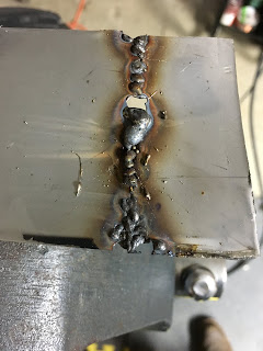
Some tac welds in the .025" SS.

It was easy to blow through using .030 wire.  I should have had .025".

One hole was drilled for the butterfly shaft and then then where to drill the opposite hole was found with a folded piece of paper.

Drilling stainless is a pain.   The drill bits love to grab when they finally break through.  Backing up with wood helps.

I cut a tube at an angle and traced around it to make a pattern for the butterfly.

The butterfly template.

The installed valve.   Riveted baffling material makes the flexible gasket on the butterfly.  A drilled brass rod secures the butterfly.   The valve fits snuggly.

Engine side view.   It's slightly egg shaped but a hose clamp on the scat tube forces it round.


Thursday, March 25, 2021

Chapter 22 Dynon AP Servo wiring


The autopilot servo (SV32 and SV42) wiring is different from other Dynon network cables.   Power and the yellow disconnect wires are not connected to the network.   Since the network is a party line, I combined /spliced the data pairs to make a Y cable.   The diagram below was followed except one of the right hand female connectors was eliminated by splicing the data pairs together.


Tuesday, March 9, 2021

Chapter 22 - Electrical System - VPX installation


A couple 1" and 2" pieces of angle are held by screws with locking nuts to the center stack.  Nut plates were installed on the bottom side.  The VPX mounting bracket was used to accurately locate the mounting holes.


An angle bracket attaches to the bottom lip of the instrument panel.   The other end attaches to F28, leaving enough clearance for the IP cover's flange.  6 nut plates were used.


I'm installing terminal strips to terminate the VPX leads to for easier maintenance and flexibility.  A location above the VPX will keep the leads short so disconnecting the connectors and removing a few screws will make it easy to remove or replace the VPX if needed.  I marked a spot on the center stack where a nut plate will be located.

A punch in the mark to keep the drill bit from walking.

A #19 bit hole for the nutplate jig is made.

The locating peg is placed in the #19 hole.

The top #40 hole is drilled next.

The jig is flipped over, with the #19 and #40 holes used as a guide for the jig and the second #40 hole is drilled.

The center hole is enlarged.

A countersink with a #40 pilot is used to deburr and countersink the holes for the flush rivets.

The appropriate length rivets and nut plate is installed.


Bracing and more nut plates are added to support the outboard side of the terminal deck.  J12 is populated with #16 wire to the terminal.  Smaller wire if appropriate can be run from the terminal to the load.  If I was super weight conscious, direct wires could be run to the VPX to eliminate the terminals.  Holes were drilled along the edges to accommodate ties or lacing tape to secure the wires.   

J1 is the only connector not terminated and is wired directly to the EFIS.  J2 only has 19 wires (no connection to pin 13), so uses two 12 connection terminals.


View from the pilot side.  I opted not to use the center stack as the inboard support for this tray so the avionics could be removed as a group.