Almost per plans...
*another update....a couple cracks appeared on the #1 & #4 baffles. It's probably because I put those parts under the #2 & #3 baffles and screws which pinched and stressed the parts. They should have gone on the outside so cylinder head movement wouldn't crack them. Here's what I did ...
https://cozy1537.blogspot.com/2023/11/baffling-cracks.html*update... See the updates for First Edition plans/Mandatory changes. The exhaust baffles should be made with 1/8" aluminum. This update isn't in the Third Edition Plans.
http://www.cozybuilders.org/newsletters/MKIV_corr_by_chap.html
Vance and others suggested using .032 aluminum instead of .025 to reduce cracking. Some posted they got the Vans kit and only used some of the parts.
I started making baffles using the plans but with tapered fins on the cylinder barrels, will have to modify the cylinder fin baffles.
Here's a template for ECI tapered cylinder baffles if using the Vans baffle kit:
http://www.prettybits.com/files/Tapered_Cylinder_Baffle_Extensions_Continental-ECi.pdf
https://images.app.goo.gl/SgHcrgonccf1auMb6
The first parts were fairly easy to make.
 |
| Put the #1 & #4 baffles on the outside of #1 & #2 to allow for expansion otherwise they'll crack near the screw. |
 |
| The top cowl makes contact. It's easy to see in the rear of the cowl. |
 |
| I used a sharpie on a stick to mark cut lines. Initially I trimmed for 1/4" clearance but later, the plans specify 3/4 to 1.5" clearance over the heads to allow for engine movement. |
 |
| A typical problem I have is getting tired and making mistakes. I was using the small M drawing and didn't realize that this template and was split onto another page. |
 |
| The plans template was close but I changed the cut/bend lines a little to match these heads better. I'll round the corners, debur and sand the edges. |
 |
| Nutplates were installed on the #3 cylinder head baffles to help hold the forward sections in place. |
 |
| Nutplates installed on #4 cylinder head baffle. |
 |
| Another area the plans templates don't match due to a different starter and alternator. |
 |
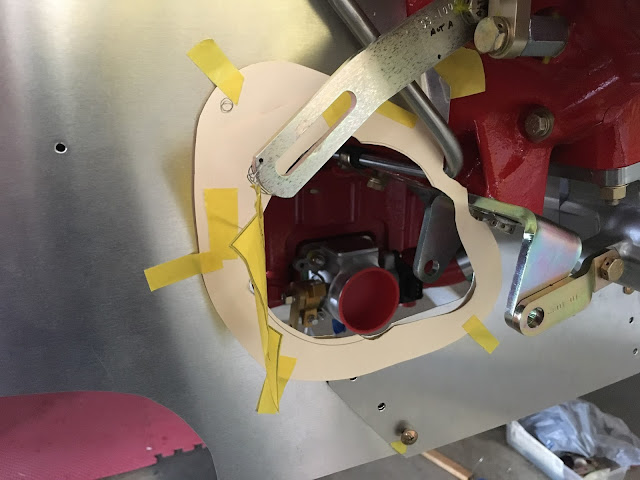
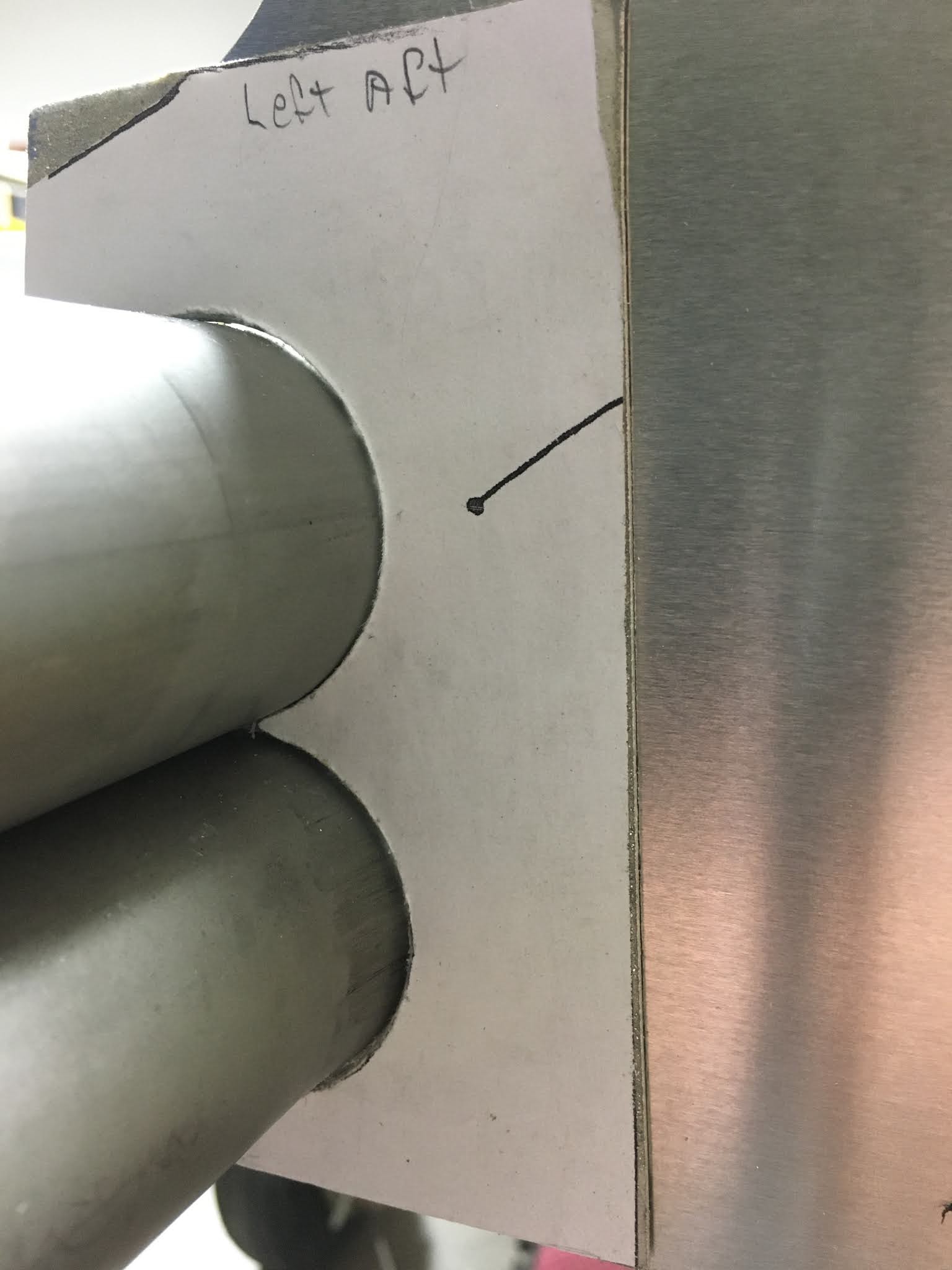
| The plans template didn't quite match the #4 exhaust pipe so I used some scissors and tape to adjust the template. The SDS fuel injector protrudes. |
 |
| The band saw has size/width limits of a little over 13". |
 |
| The aft baffle at the #1 cylinder. |
 |
| A bottom baffle support bracket that bolts to the starter. (Not in the plans) |
 |
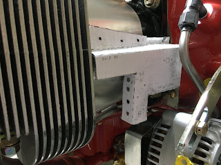
The top left brace was added to stabilize the top of the aft right baffle. The per plans baffles would be attached in this area.
 |
 |
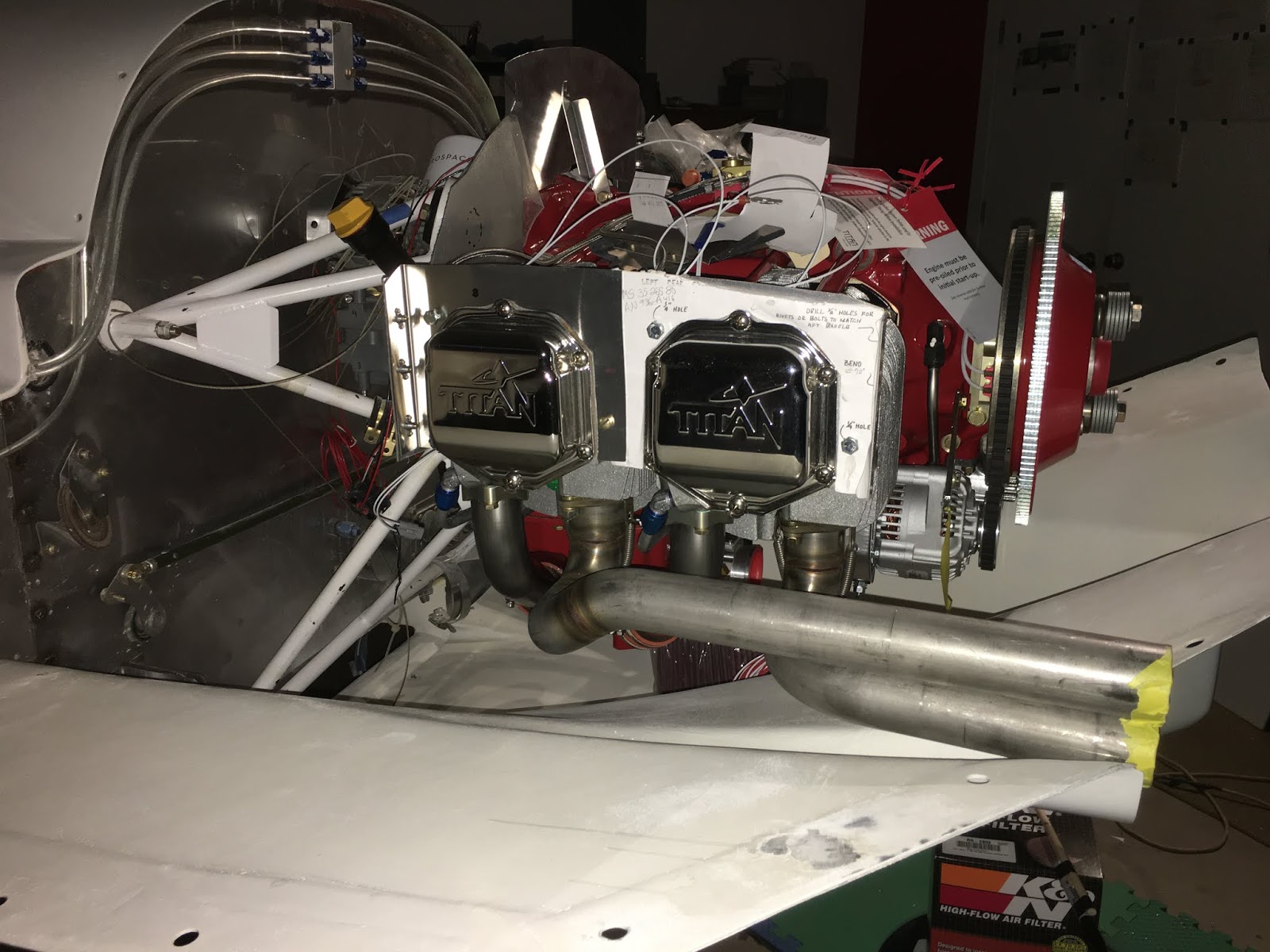
| Tapered baffles with the hanger reinforcement wire and small beads of silicone adhesive to reduce abrasion. |
 |
| Safety wire routed through some Nylaflow. |
 |
| Modified M34 #6 template. |
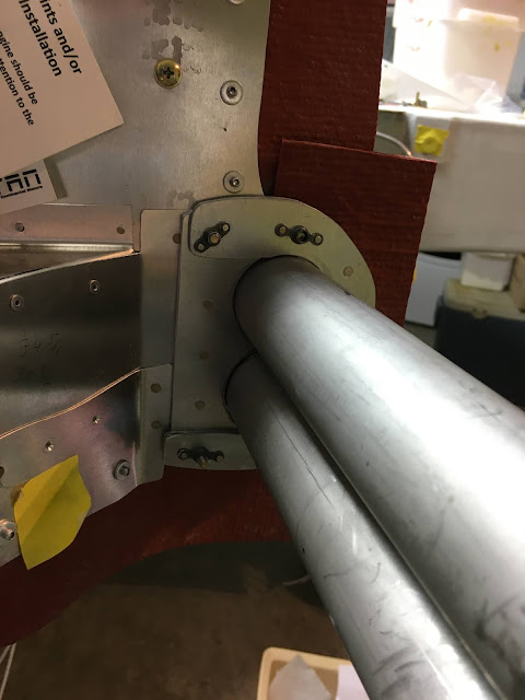
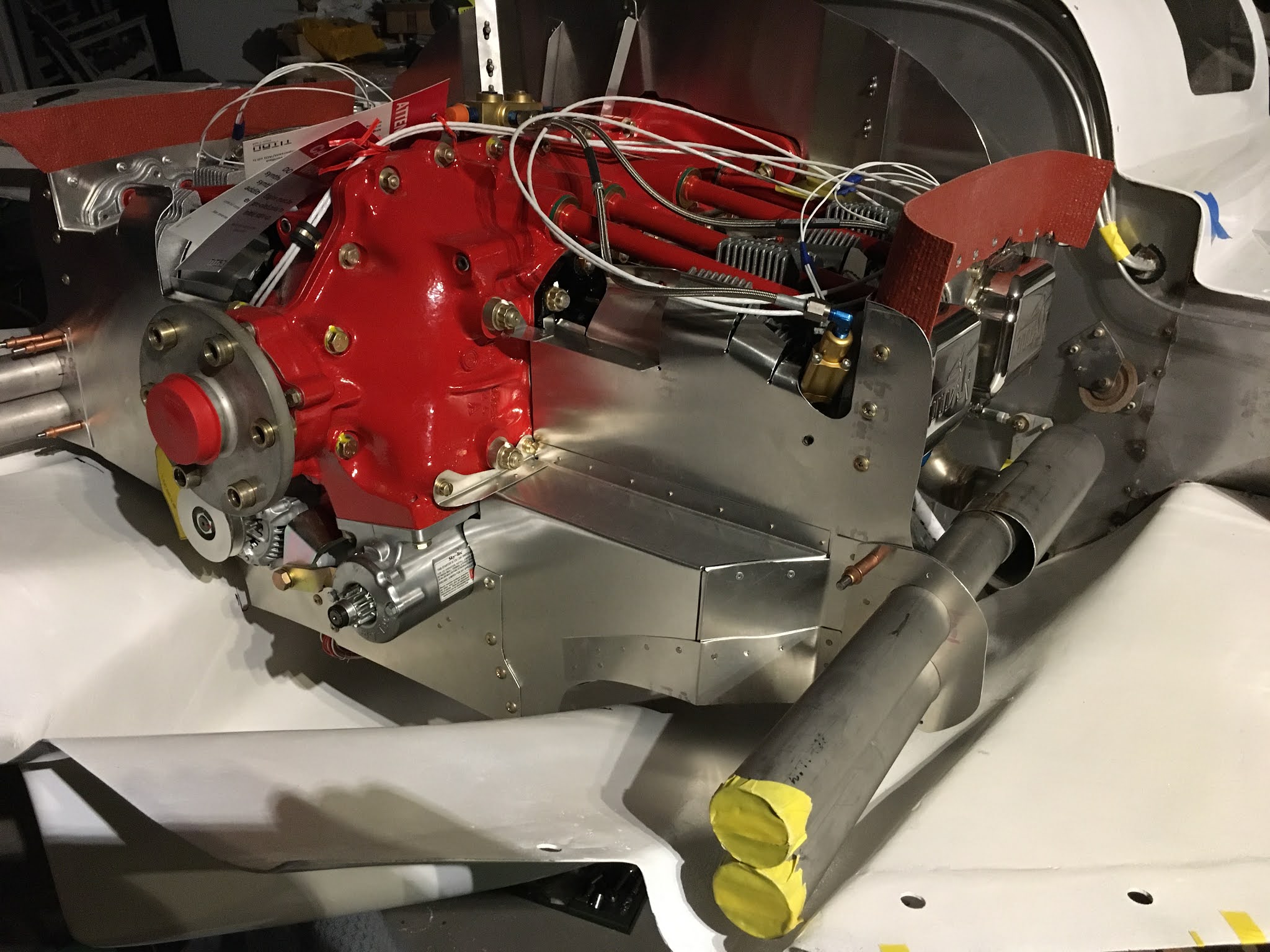
The pipe here goes to the prop governor.
There's a 1/4 x 20 hole on the case behind the alternator, so made a bracket to hold the barrel baffle and have a place for a nutplate to help secure the aft baffle.
|
| This one is per plans. It wasn't clear to me what/how to use two double loop safety wires so I twisted to .041 wires together as one and threaded it through the 1/8" holes. |

A nut plate jig (they're not cheap) makes perfect holes. There's no nut plate jigs for the small footprint nut plates though.
|
 |
A template posted on the RV forum was used for the barrel fin baffles.
 | The modified template #1 was used to make the interhead baffle #6.
|
 |
The intercylinder head baffle is not per plans but is similar to the plans part on the left side of the photo.

The right aft baffle's movement was limited by adding a piece that stops against the spacer on an engine through bolt. Dabs of RTV will be used to stop rattling and wear.

 |
Alternator collar template.
|
Heavy aluminum tape was used to seal around the alternator and starter. Some large washers capture the collar around the starter.


 Heavy aluminum tape was used to seal around the alternator and starter. Some large washers capture the collar around the starter.


No comments:
Post a Comment