Thursday, January 31, 2019

2019 01/31 Panel Planner


This morning I opened Panel Planner to update the file to increase the clearance for the radio cage tray screws.  It is quirky software.  I've emailed support months ago about some of the issues but never gotten a response.   One problem is the Dynon Knob panels aren't all correct.   The only one that seems to be right when viewing the cut out mode is the Autopilot panel.  The lower rectangle is the Radio Knob panel.   I'd be pretty irritated if I gave the .dxf file to someone to cut a panel and hadn't caught this.   Occasionally, clicking/selecting an object causes it to move.  Sometimes selecting multiple objects and trying to move them as a group has unexpected results.   The undo feature doesn't seem to always work.  I've learned to save files often in order to have a back up.   Another major annoyance is the software has to be run as administrator on Windows.  I'm not an expert with this software so maybe some issues are caused by the user.


The fuel pump installation is almost complete.  The hard points are floxed in and cured.  The thigh support ribs are glassed in and curing tonight.  Searched the builder group for thigh support issues and found that the plans need corrected and it has been discussed.  I noodled the idea of cutting the thigh supports and lower instrument panel to make the leg openings larger but decided that might be a mod to do later on.  I've been eyeballing where and how to mount the high pressure gascolator and fuel pressure regulator and also working on the throttle cable support.

2019 01/30 Parts run & Fuel Pump mounting

Downtown Fort Worth

Yesterday, my friend & I flew over to Lancaster and visited ASOD (Air Salvage of Dallas).  A visit had been on our bucket list for awhile.   A mixture cable was acquired that should work as the throttle cable. It was chilly for Texas, but the heater works good in his bird.  

I've tried a few solutions to use as hard points.  Tack welding a nut to a washer was one thought.  Pretty easy to blow through the side of these little nuts though.
A washer hole drilled out to 1/4" and a #8 Rivnut allows for a little tolerance since the AN3 bolts or Clickbonds are to large for the fuel pump.  These aren't locking threads so I'll use blue Locktite on the screws when the pump is installed.
Floating nut plates riveted to some .063 6061 was another considered.
I opted to use the Rivnut/washer solution.   The screw holes penetrate the bottom skin so will double as drain holes if necessary when doing maintenance.  Flox and BID will secure the fasteners.  The screws will be flush with the bottom skin.

Test fit before floxing and glassing.


Monday, January 28, 2019

2019 01/28 Radio cage/Dynon knob panel clearance and bezel depth

Bezel depth measured:
Skyview HD Display bezel is .45"
SkyView Knob Panel .16"
PS Engineering Audio panel .6"
Avidyne Nav/Com .7"

PSE tray screw length is .5"  <------Doh!   Might be able to use flush rivets, but probably better to increase the knob panel gap to the radio cage/center stack.
Some trays are 6.3" wide and others are 6.25" wide.  The bezels of the equipment are also different.   Pretty common to see gaps, uneven vertical gaps and bezel's that aren't flush on older panels:


The take away from these measurements is that the bezels won't be flush with each other without careful planning.   The cage can be constructed so the mounting clips allow the trays to slide in and out a little.   The Dynon knob panel will need a spacer to bring them out flush with the Nav/Com or HD Display.

The knob panel bezel will need to be far enough from the radio cage to accommodate .5" tray screws.  This will result in at least a .4" gap between the knob panel and Nav/Com bezels.


2019 01/27 Mocking up the Instrument Panel

In the past couple of days I continued to work on smaller tasks.  I listed all of the tasks that I know I need to complete and made a list of milestones.   "Panel Working" is the next milestone.   At this point in the project, a Gantt Chart would be helpful at times because as I look at the task list, I'm seeing "this needs to be done before that" for a lot of items.  I ran into a stopping point on some tasks because of needing some parts that are on order.   


Based on this mock up panel (no fancy tools were used to make this...just marked and cut with a Fein Tool and Uni-bit), looks like there's capacity for 90 circuit breakers and switches using the standard holes.   A friend with extensive avionics experience cautioned me to "allow for expansion.  There's always something new to add later on."

Found that "thickness matters.   The breaker switch's necks are only .3" long.  I removed one layer of ply to get some surplus test breakers mounted.  Then I asked my buddy if this was enough.  Vance commented, "Know you know why I have breakers and knobs all over my panel."

One of the knob panels is slightly rotated and one of the breaker holes is a touch high.   Not bad for cutting by hand though. I'll check with a local shop tomorrow about CNC cutting a panel.  I'm using the "Panel Planner" software you can get "free" if you buy $7500 worth of avionics from ACS, so can generate a DXF file for them to use.

Fits here....  The original panel is a little over .25" thick.  Not an issue for the displays, but it is for the switches and center stack cage even with a .063" aluminum panel.

My early version 2 panel will have three trays in it, but later will reduce it to two trays.   I'll explain more later...  Anyway, the cage needs to be taller, so will take out a portion of the bottom rows of holes to accommodate the top tray.

I'd planned on having the bezels nicely fitting together, but as my friend points out...."these vendors do their own thing".  Case in point, the PSEngineering Audio Panel would set in further than the Nav/Com if  using the front edge of their tray as a guide.  So mounting the audio panel tray a little further forward will put it flush with the Nav/Com.   Some of the trays are 6.25" wide and some are 6.3" wide.  Just enough you notice it if you look for it.  I need to increase the space between the knob panels and center stack enough to accommodate the screws that secure the trays to the cage.  An alternative would be to use flush rivets and keep this spacing.

Having an expert provide guidance and wisdom saved me some headache.  You can see where one ply was removed so the short necked breakers could be mounted and checked for clearance. 
I still need to cut the vents, USB charging ports, remote ELT panel etc.   Also the center console area that joins to the panel will be constructed and filled with the SDS programmer, mixture knob and maybe the landing gear and brake switches in an attempt to have a nice flow for GUMPS.

It was a nice day and got to go for a nice ride with some friends. We flew over an airpark called Driftwood and then got fuel at XBP which is a municipal airport with adjacent airpark property.  Coming back to my home field was pretty busy.  ADS-B was helpful spotting a lot of aircraft but we still saw others that weren't ADSB-out. 

Friday, January 25, 2019

2019 01/25

One of the things emphasized at the engine build school was to apply the proper amount of dope/sealant/lubricant to assembled parts.   The inspectors did not like to see messy plugs, nipples, threads and other parts. 

The procedure to neatly apply the proper amount is to apply the dope to the 2nd thread from the bottom.   Doing this will avoid pushing excess material into the fuel and oil lines.  On critical systems such as fuel injection, if you remove bushings or nipples, you need to clean the threads to avoid pushing the older stuff into the lines when you screw the parts back in.  Teflon tape does not belong here.

On the valley of the 2nd thread from the bottom, apply a light streak of pipe dope using a small wire or toothpick.
After screwing in the nipples, you can see there was just the right amount of dope that rolled onto the fittings.  


Wednesday, January 23, 2019

2019 01/23

We've been traveling a bit (thousands of miles in winter conditions) so haven't worked on the project for a few days.  


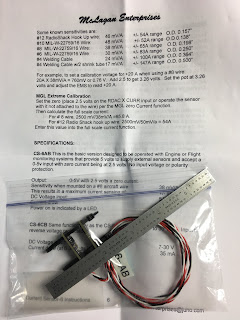
I had some equipment arrive which included a Hall Effect Amp sensor (photo below).  ACS part number 11-13991.

It would be nice to monitor the alternator outputs, but also nice to see the load on the system.  I'd read where someone was going to use one sensor on two cables from the alternators.  I wonder how accurate that would be, but maybe just confirming that each of the alternators is producing power is good enough. 

The sensitivity chart shows more millivolts per amp on smaller wires which is because the magnetic field is more intense around a smaller wire carrying one amp than a larger wire carrying one amp.

I'd asked ACS about using this with SkyView and they recommend the shunt and I'm guessing it's because it will require calibration.  

Several advantages of these are it eliminates more junction points in the lines or cables where the shunt is installed and reduces exposure of the battery voltage to unintended shorts to ground (like errant wrenches).   To install, just put each small circuit board on opposite sides of the cable, tighten the cable ties and put clear heat shrink over it.

Disadvantages are that this requires a 5 volt power source.   If the glass panel dies, so does the ammeter.   Calibration will require temporary use of a test ammeter.  Should not be mounted in the engine compartment.


High Sensitivity Amp Sensor

Also received some 25 Amp toggle panel switches that were surplus for $.60 each from Del City.   They seem to be decent quality but have solder terminals instead of screw.   I've got some of the breaker switches from ACS for about $25 each and it looks like the price has recently gone up on them.


Tuesday, January 15, 2019

2019 01/15

Andair Dual Gang Fuel selector valve, SDS fuel pumps, 40 micron fuel filter.   Click bonds will be used to secure the fuel pump. *Update-Click bonds were to large so I used rivnuts secured to washers that are floxed into the floor.   The thigh support will be secured with hinge pins to allow access for maintenance.
Completed another leak test and repaired a small leak on the left tank where the fuel probe line came in under the longeron.


Pilot side of valve/banjo valves.

Close up of lines and banjo valves.


Matco brake lock valve had some metal shavings in it.   Need some AN-3 1/8" nipples and cable to complete its installation near the pilots left leg.

Monday, January 14, 2019

2019 01/14

Updated the blog reference links at the bottom of this page.  Added links to the Cozy Builder Map and Google Drive info.   I'm not sure how to find this info without bookmarking it.

Helped Vance with some minor tasks on his Cozy this morning.
Had Vance and another friend look over my progress.
Got updates on orders and will be getting seat foam and other parts tomorrow.

Will go spend a few more hours tonight completing a few of the many unfinished tasks.

2019 01/13

Partially installed the Matco Parking Brake valve.   (Ordered some AN-3 nipples) to complete the install.

Also need to order a cable for the brake lock.

Measured the outer cable shield distance from the throttle quadrant to the butterfly at 86-89".  Travel to fully open/close is 2" or 2.5" depending which hole is used in the butterfly.

Ordered AN-4 1/8" fittings for the fuel vent line termination into the firewall manifold.

Futzed with wiring for awhile.   Would be nice to use a 90 degree back shell for some of the Dynon DB 9 connectors to reduce the depth clearance.

Started prepping the copilot thigh support ribs to be glassed in since the fuel lines and selector are plumbed.

Sunday, January 13, 2019

2019 01/12

Another chilly day outside.  Not bad inside the hangar.

Tightened some of the firewall motor mount bolts. 
Helped Vance with a few things on his Cozy this afternoon.
This evening, ran some of the SDS wires to the front console:
2 DB 9 cables that go to the programmer
2 blue LOP wires (primary and back up)
Fault LED wire (from primary ECU pin 11)
Shielded 3 conductor mixture knob wires.

Remaining wires that need to run to the front from the hell hole:
Injector selector switch
ECU primary and back up power
Air Brake Actuator
Roll Servo network and power
ELT wires
Dynon  SV-220 (sensors interface unit) network wires
Fuel site gauge illumination LEDs.

Also need to connect and mount the Princeton fuel probe modules.
A Hall Effect amp sensor (on order) will be used instead of a shunt.

Friday, January 11, 2019

2019 01/11

I've worked on a variety of things this week while waiting for orders to arrive.

Mounted the oil temp sensor in the 90 degree oil filter adapter.
Terminated the SDS (Bosch) throttle position sensor.  I crimped the wires but ended up soldering them since I could pull the wires out of the crimp.
Installed the P5000 quick oil drain plug.
Finished making the cabin fuel lines and leak tested the fuel selector/lines and tanks.   Found air leaking from the left tank where the fuel probe line came through under the longeron.   Drew a vacuum on the tank, used a hypo to fill the leak with epoxy.

Started eyeballing how/where to mount:
18 row oil cooler (near the plans location -top cowl-should work)
3 MAP sensors (2 for SDS, one for Dynon)
SDS Intake air temp sensor
Oil and fuel pressure sensors.
Fuel pressure regulator.
Battery and Starter solenoids.
Throttle quadrant/cable.


Glanced at the Aveo Ultra strobe/nav lights manual and noticed they are TSO'ed.
Copied the XP-382 engine manual and Aveo light manual to Google docs and linked them to blog entries. 

Contacted Ross at SDS about several items.   I was missing some of the male Weatherpak pins needed for the injector harness and also had questions about which Hall Effect sensor should connect to the primary ECU and which one should go to the back up.   Ross offered to send some pins and advised that the calibration procedure would synch the sensor with the ECU.   I think when we ran the engine at Kamloops, the top sensor went to the primary ECU.   They kept the harness for the test stand and replaced my connectors which is why I can't tell.   I should have pins here on Wednesday from another vendor.

I'd ordered about 15 items on-line through AeroPerformance for "will call pick up" and had checked on delivery.   A bunch of the items had not been processed, but some were.   I don't quite understand why everything wasn't ordered but the local gal at the counter advised me next time to let her know and she'd get everything ordered.  I wanted to pick up at the store to avoid having packages delivered during the holidays when we were gone.

Del City has a bunch of overstock/discontinued items so I ordered a bunch of switches that are normally $4 for .60 each.   I was pondering getting a 60 amp breaker rather than using the ANL fuse.

My Nav/Com was shipped but there was a snafu on the delivery address.   UPS shows they received an address update but also show delivery tomorrow.

It's been cold and rainy, but the heater is keeping the shop above 60.  There's been respiratory crap going around and it finally caught up with me.